
Closed circuit
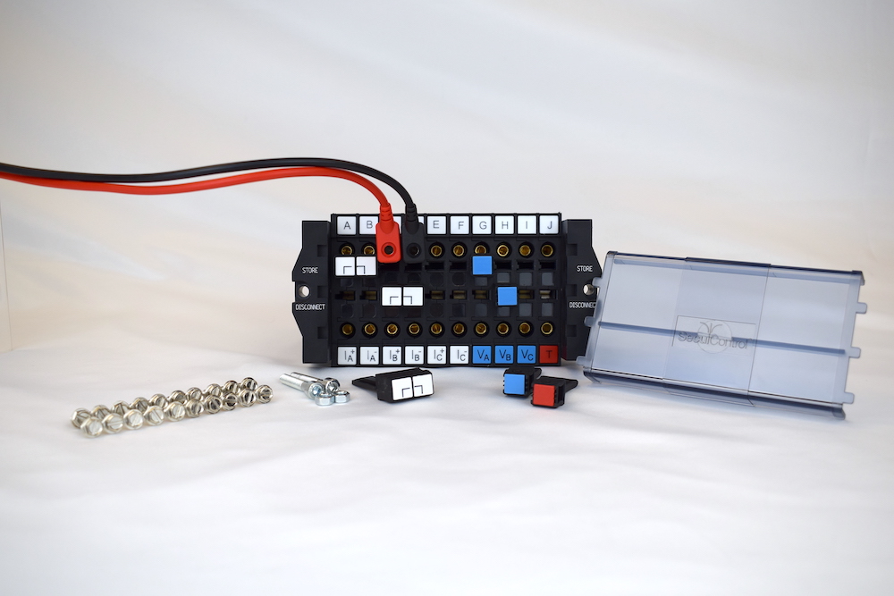
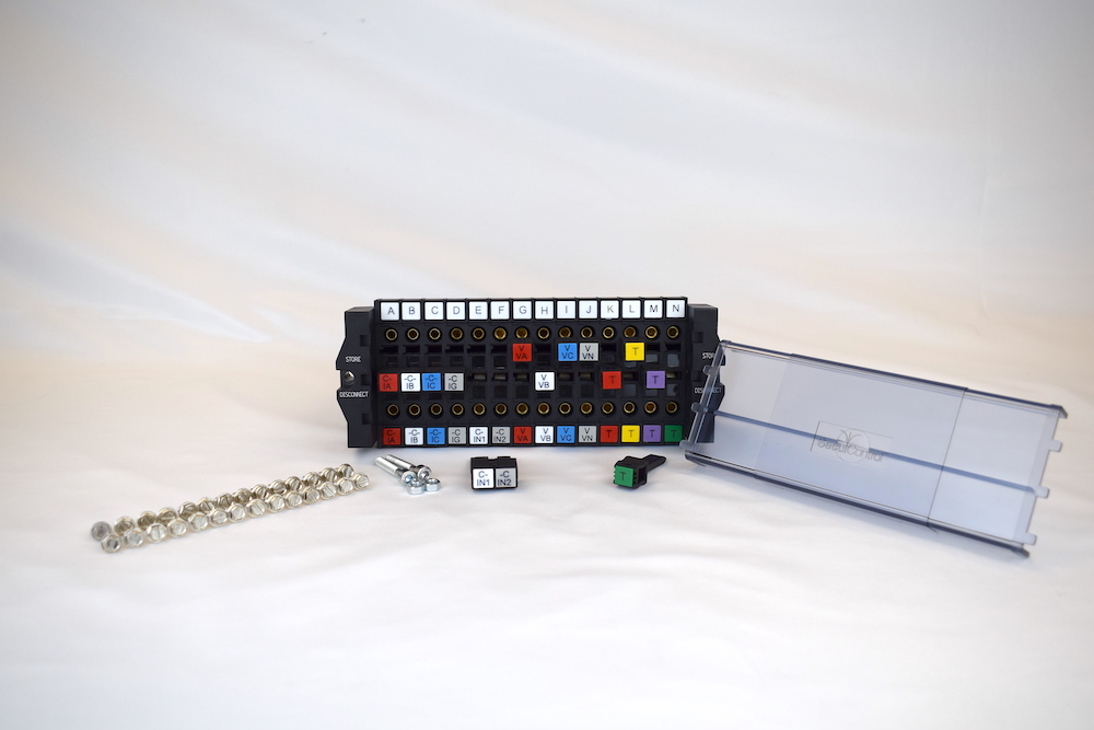
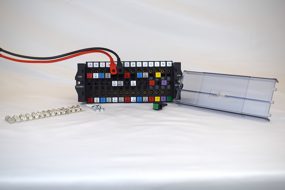
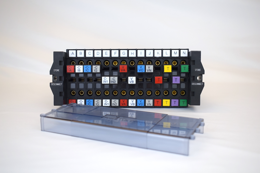
An ST Switch contains any even number of poles within the range of 4 and 20, each allocated to a current, voltage, signal or trip circuit. Each circuit is connected through the block via two silver-plated copper contacts, pressed securely together by two pressure springs to create a highly conductive electrical connection. In this situation, a electrical connection is established between the device side (B) and the system side (A).

Open Circuit
To open one of these modular poles, a disconnect pin is removed from its inactive “parking” position and inserted between the silver-coated copper contacts (the “test” position). In this position, the device and system sides of the test block are isolated from each other. For current circuits, the disconnect pins include internal shorting bridges. When the pin is moved back to the “parking” position, the internal springs force the contacts back together, returning the circuit to its normally-closed position. There is no in-between position, completely eliminating the risk of accidents resulting from improperly closed circuits.
For technical documentation and product details, please reach out via email or our contact form.
Click here to connect with our team.
Other documents: